What is an Entity Relationship Diagram (ERD)?
Entity Relationship Diagram (ERD) is a visual tool used in software engineering to model and design databases. ERD represents the relationship between various entities in a database system, as well as the attributes of these entities and their interactions. ERD provides a standardized approach to database design and serves as a communication tool for developers, stakeholders, and end-users. It enables developers to understand the requirements of the users and design a database that meets those needs. ERD is an essential component of software engineering, particularly in developing complex database systems.
Purpose of ERD
- The construction of an ERD helps the database analyst to gain a better understanding of the data that will be stored in the database.
- ERD can be used as a communication tool between the development team and stakeholders. By visualizing the data model, stakeholders can understand the database structure and provide feedback on any changes or improvements that need to be made.
- The ERD serves as a documentation tool, providing a visual representation of the database structure.
- The ERD is used to connect the logical structure of the database to users, effectively communicating the database logic to them.
- ERD can aid in the identification of potential design flaws and inconsistencies in the data model. This helps in identifying and fixing problems before implementation.
Components of ER Diagrams

Entity
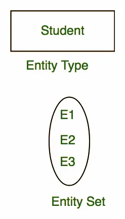
Entities are the building blocks of an Entity Relationship Diagram (ERD). They can be either animate or inanimate real-world objects that are easily identifiable. In an ER diagram, entities are represented as rectangles. For example, in a school database, entities can be students, teachers, classes, and courses offered. Each entity has specific attributes or properties that give them its unique identity.
Entity sets are a collection of related types of entities in a database. They may contain entities with attributes sharing similar values. For example, a Student set may contain all students of a school, while a Teacher set may include all teachers of a school from all faculties. Entity sets may not necessarily be disjoint and may overlap with each other. ERDs use entity sets to define relationships between entities and help to create a conceptual data model of the information system.
Attributes
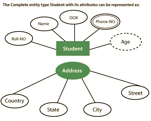
In ER modeling, entities are represented by their properties, which are called attributes. Attributes have values associated with them. For example, attributes of a student entity could be name, class, and age. Attributes have a domain or range of values that can be assigned to them. For instance, a student’s name must be alphabetic, and their age cannot be negative.
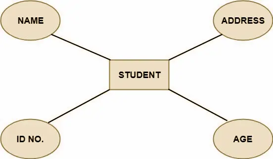
Below are the different types of attributes:
- Key attribute
- Composite attribute
- Single-valued attribute
- Multi-valued attribute
- Derived attribute
Key Attribute: A key attribute is an attribute or group of attributes that can identify an entity uniquely in the entity set. In other words, a key attribute can distinguish an entity from other entities. For instance, the roll number of a student can serve as a key attribute, allowing him or her to be identified distinctly among all other students.

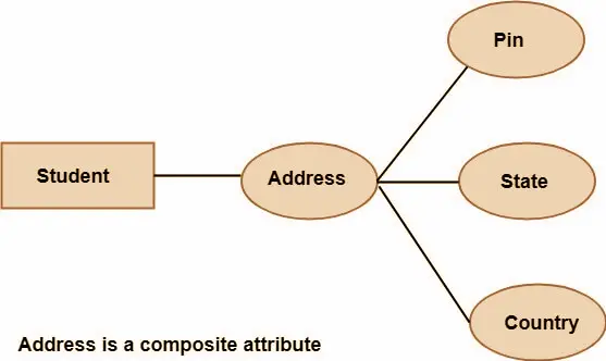
Composite Attribute: A composite attribute is a type of attribute that is formed by combining other attributes. In the context of a student entity, the student’s address is an example of a composite attribute since an address is made up of various components such as the pin code, state, and country.
Single Valued Attribute: A single-valued attribute is an attribute that can contain only one value. For instance, Social Security Number can be considered a single-valued attribute.
Multi Valued Attribute: When an attribute can have multiple values, it is referred to as a multi-valued attribute. These types of attributes are represented by a double ellipse in an ER diagram. An example of a multi-valued attribute is a person’s phone number or email address, as one person may have more than one phone number or email address associated with them.

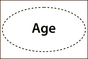
Derived Attribute: Derived attributes are those attributes that are not stored in the physical database but are obtained from other attributes present in the database. These attributes are represented by a dashed ellipse in the ER diagram. For instance, age can be derived from the date_of_birth attribute.
Relationships
In the field of entity-relationship modeling, a relationship type signifies the association between two or more entity types. For instance, the “works for” relationship type exists between the Employee and Department entity types in an organization. The ER diagram represents the relationship type using a diamond shape, which connects the entities through lines, indicating their association. The collection of all instances of a particular relationship type is known as a relationship set.

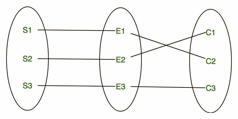
The term “relationship set” refers to a group of relationships that share the same type of association between entity types. In the context of an ER diagram, relationship sets are represented by a diamond shape and lines connecting the entities. For example, a relationship set “Enrollment” may include the relationships S1 enrolled in C2, S2 enrolled in C1, and S3 enrolled in C3.
Degree of Relationship Set
The degree of a relationship set refers to the number of participating entities in a relationship. There are three common types of relationships in E-R models, depending on their degree:
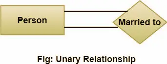
- Unary relationship, also known as a degree 1 relationship, involves a single entity participating in the relationship.
- Binary relationship, also known as a degree 2 relationship, involves two entities participating in the relationship.

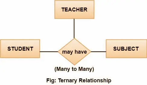
- Ternary relationship, also known as a degree 3 relationship, involves three entities participating in the relationship.
Cardinality
Cardinality defines the specific number of entities that can be associated with other sets of entities via a relationship set in an ER model. It determines the nature of the relationship between entities and can be categorized into different types, such as one-to-one, one-to-many, and many-to-many. The cardinality of a relationship set is essential in determining the optimal design of the database schema.
Types of Cardinalities
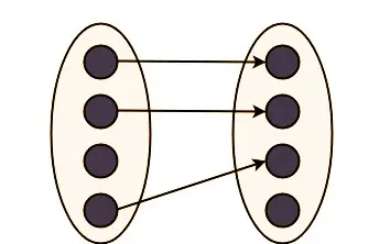
- One-to-one cardinality refers to a type of relationship where one entity from entity set A can be associated with at most one entity from entity set B, and vice versa. For instance, if each student in a school database is assigned only one student ID, and each student ID belongs to only one person, the relationship between the two entity sets will be one-to-one.

Using Sets, it can be represented as:
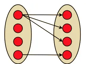
- One to Many – When one instance of an entity set is associated with multiple instances of another entity set, it is referred to as a one-to-many relationship. For instance, a customer can place multiple orders, but each order can be placed by only one customer.

Using Sets, it can be represented as:
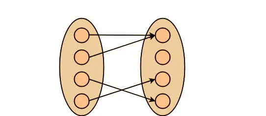
- Many to One – In a many-to-one relationship, multiple entities from entity set A can be associated with at most one entity of entity set B, while an entity from entity set B can be associated with more than one entity from entity set A. For instance, multiple employees can work in a single department, but each employee works in only one department.

Using Sets, it can be represented as:
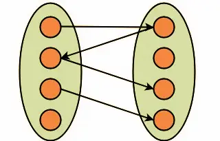
- Many to Many – In a many-to-many relationship, each entity from entity set A can be associated with multiple entities from entity set B, and vice versa. For instance, a student can be enrolled in many courses, and a course can have multiple students enrolled in it.

Using Sets, it can be represented as:
Keep checking our tutorials.freshersnow.com frequently to get the latest updates on Entity Relationship Diagram (ERD).
